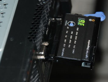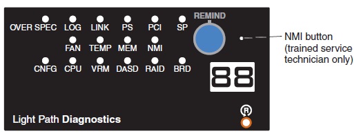

OVERSPEC
There is insufficient power to power the system. The LOG LED might also be lit.
1. Add a power supply if only one power supply is installed.
2. Use 220 V ac instead of 110 V ac.
3. Reseat the following components:
a. Power supply
b. Power backplane
4. Remove optional devices.
5. Replace the components listed in step 3 one at a time, in the order shown, restarting the server each time.
LOG
Information is present in the BMC log and system-error log.
1. Save the log if necessary and clear.
2. Check the log for possible errors.
LINK
There is a fault in an SMP Expansion Port or SMP Expansion cable (requires scalability enablement).
Notes:
1. This LED remains lit until the problem is resolved and the server is turned off and restarted.
2. If a fault occurs, the SMP Expansion Port link LED on the failed port is off.
1. Check the SMP Expansion Port link LEDs to find the failing port or cable.
2. Reseat the SMP Expansion cables.
3. Replace the SMP Expansion cables.
4. (Trained service technician only) Replace the microprocessor board.
PS
A power supply has failed or has been removed.
Note: In a redundant power configuration, the dc power LED on one power supply might be off.
1. Reinstall the removed power supply.
2. Check the individual power-supply LEDs to find the failing power supply.
3. Reseat the following components:
a. Failing power supply
b. Power backplane
4. Make sure that the power cord is fully seated in the power-supply inlet and the ac power source.
5. Replace the components listed in step 3 one at a time, in the order shown, restarting the server each time.
6. Disconnect the ac power cord for 20 seconds;then, reconnect the ac power cord and restart the
server.
PCI
A PCI adapter has failed.
Note: The error LED next to the failing adapter on the I/O board is also lit.
1. See the BMC log or the system-error log.
2. Reseat the following components:
a. Failing adapter
b. I/O board shuttle assembly
3. Replace the components listed in step 2 one at a time, in the order shown, restarting the server each time.
SP
The Remote Supervisor Adapter II has failed or is missing or the planar cable is not connected.
1. Reseat the Remote Supervisor Adapter II and planar cable.
2. Update the firmware for the Remote Supervisor Adapter II.
3. Replace the Remote Supervisor Adapter II.
FAN
A fan has failed or has been removed.
Note: A failing fan can also cause the TEMP LED to be lit.
1. Reinstall the removed fan.
2. If an individual fan LED is lit, replace the fan.
Note: A failing fan might not cause the fan LED to be lit.
3. Reseat the microprocessor board.
4. (Trained service technician only) Replace the microprocessor board.
TEMP
A system temperature or component
has exceeded specifications.
Note: A fan LED might also be lit.
1. See the BMC log or the system-error log for the source of the fault.
2. Make sure that the airflow of the server is not blocked.
3. If a fan LED is lit, reseat the fan.
4. Replace the fan for which the LED is lit.
5. Make sure that the room is neither too hot nor too cold.
6. If one of the VRMs indicates “hot,” remove ac power before you restore dc power.
MEM
Memory failure.
Note: The error LED on the memory card is also lit.
1. Remove the memory card that has a lit error LED; then, press the light path diagnostics button on the memory card to identify the failed card or DIMM.
2. Reseat the DIMM.
3. Replace the following components one at a time, in the order shown, restarting the server each time:
a. DIMM
b. Memory card
c. (Trained service technician only) Microprocessor board
NMI
A hardware error has been reported to the operating system.
Note: The PCI or MEM LED might also be lit.
1. See the BMC log and the system-error log.
2. If the PCI LED is lit, follow the instructions for that LED.
3. If the MEM LED is lit, follow the instructions for that LED.
4. Restart the server.
CNFG
A configuration error has occurred. 1. Find the failing or missing component by checking the other light path diagnostics LEDs.
2. Make sure that the fans, power supplies, microprocessors, VRMs, and memory cards are
installed in the correct sequence.
CPU
A microprocessor has failed, is missing, or has been incorrectly installed.
1. Make sure that the microprocessors are installed in the correct sequence
2. Check the BMC log or the system-error log to determine the reason for the lit LED.
3. Find the failing, missing, or mismatched microprocessor by checking the LEDs on the microprocessor board.
4. Reseat the following components:
a. Failing microprocessor
b. Microprocessor board
5. Replace the following components one at a time, in the order shown, restarting the server each time:
a. (Trained service technician only) Failing microprocessor
b. (Trained service technician only) Microprocessor board
VRM
A dc-dc regulator has failed or is missing.
1. Check the BMC log or the system-error log to determine the reason for the lit LED (for a VRM).
2. Find the failing or missing VRM by checking the LEDs on the microprocessor board.
3. Install any missing VRMs.
4. Reseat the following components:
a. Failing VRM
b. Microprocessor associated with the VRM
c. Microprocessor board
5. Replace the following components one at a time, in the order shown, restarting the server each time:
a. Failing VRM
b. (Trained service technician only) Microprocessor associated with the VRM
c. (Trained service technician only) Microprocessor board
DASD
A hard disk drive has failed or has been removed.
Note: The error LED on the failing hard disk drive is also lit.
1. Reinstall the removed drive.
2. Reseat the following components:
a. Failing hard disk drive
b. SAS hard disk drive backplane
c. SAS signal cable
d. I/O board shuttle assembly
3. Replace the components listed in step 2 one at a time, in the order shown, restarting the server each time.
RAID
The RAID controller has indicated a fault.
1. Check the BMC log or the system-error log for information.
2. Reseat the following components:
a. RAID controller, if possible
b. Hard disk drives
c. I/O board shuttle assembly
3. Replace the components in step 2 one at a time, in the order shown, restarting the server each time.
BOARD
The microprocessor board or I/O board has failed.
1. Find the failing board by checking the LEDs on the microprocessor board and I/O board.
2. Reseat the failing board.
3. Replace the failing board.


